Theoretically, if you used a 2nd microcontroller which simply pulsed an IR LED, and you aimed it directly at the Arduino with the IR receiver, you could get near DOUBLE the distance for the beam. When I tested it out, I could get a distance of 2 meters away from the IR receiver before it couldn’t detect the reflected light. This is half what the IR LED can handle when pulsed. When you pulse the current, the IR LED can handle up to 1 Amp!įor my example, I’m using a 10 ohm resistor. According to the datasheet for the IR LED, it can handle a constant current of 100mA. The 2nd circuit is the PWM for the IR LED. The output from the IR receiver is connected to the base pin of the NPN transistor. This allows a 5 Volt circuit to go through the indicator LED making it brighter, and I also use this circuit to connect to D2 for reading the signal state. To get around this, I use a 5 volt circuit going through an NPN transistor. This would be fine connecting to a 3.3 volt microcontroller, but the Arduino uses 5 Volt logic. NOTE:- the high signal is a lower voltage. When the IR light is exposed to it, the output from the TSOP38238 goes LOW. The TSOP38238 by default outputs a HIGH signal when it does not detect a 38kHz IR signal. This pin is used to generate a Pulse Width Modulation signal at a frequency of 38kHz. The yellow wire is connected to digital pin 3 on the keypad shield (access to pin D3 on the Arduino). it is used for detecting a change in the signal from the IR receiver. This connects straight to pin D2 on the Arduino…. The orange wire is connected to the digital pin 2 on the keypad shield. These tubes are IDEAL for shielding a 5mm LED!!! If you have a dog and you are a responsible pet owner, you may be familiar with the black plastic tubes which dog-poo tidy bags are rolled onto. This reflects the IR light back to the IR receiver. The light from the IR LED is then aimed at a prismatic reflector 2 meters away.

I use ‘blue-tack’ to prop a plastic tube in place to shield the IR sensor from the IR LED. The IR LED needs to be bent on a 90 degree angle so it is aimed horizontally. Jumper wires of various colours (you can get Female to Male and Male to Male).Ī prismatic reflector (You can ‘borrow’ one off a bicycle).ĥ Volt power supply (I use a powerbank and a breadboard power module). Jumper Wire 20cm Ribbon (M/F, 40pcs) Price: $3.50ġ x TSOP38238 38kHz modulated IR Receiver.ġx Any colour 5mm LED (I recommend this Superbright LED for outdoor use). I've tried using just the RFID using pin 31 without init the LCD, and the RFID is working well.PiicoDev OLED Display Module (128圆4) SSD1306 Price: $13.50 Lcd.print(millis()/1000) // display seconds elapsed since power-upĪny suggestion to make the LCD shield work together with the RFID module? Or am I doing something wrong?

Lcd.setCursor(9,1) // move cursor to second line "1" and 9 spaces over

Rfid.init() //when RFID init, LCD not working RFID rfid(53,31) //when init RFID, pin 5 changed to 31ĪnalogWrite(10, 50) // set brightness on pin 10 to 0-255
#Dfrobot lcd keypad layout code#
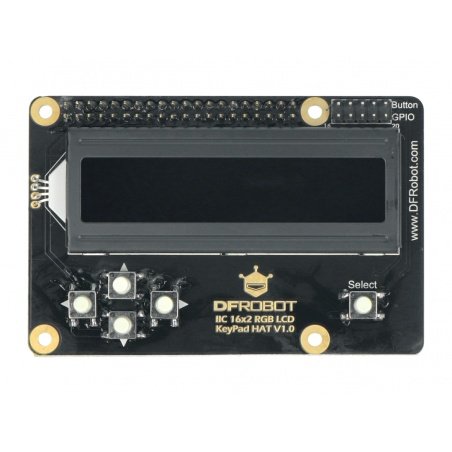
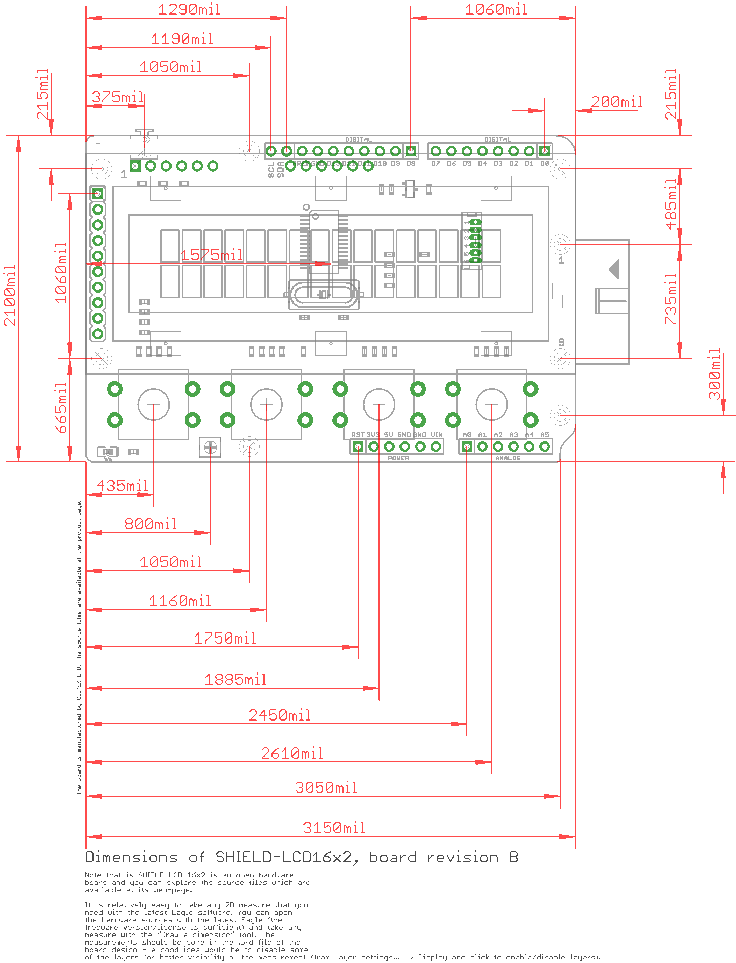
I'm using the LiquidCrystal library for the LCD, and RFID library made by Miguel Balboa () based on code by Dr.Leong (Here's some simple code I've made : LiquidCrystal lcd(8, 9, 4, 5, 6, 7) When I don't initialize the RFID, the LCD shield working well. But when I initialize the RFID and LCD shield, the LCD is not working. The problem is that the LCD Keypad shield and RFID MF522 are using pin 5 together, so I changed RFID pin to the other digital pin (I'm using pin 31 now). I'm working a project using Arduino Mega 2560, LCD Keypad Shield, and RFID 13,56 MHz MF522 module.


 0 kommentar(er)
